A tutorial on the basics and techniques of Orthographic Projection in technical drawing
Introduction
Orthographic projection is a method of representing three-dimensional objects usually by three two-dimensional drawings in which each parallel line is drawn parallel to the plane of view.
Expected Learning Outcomes
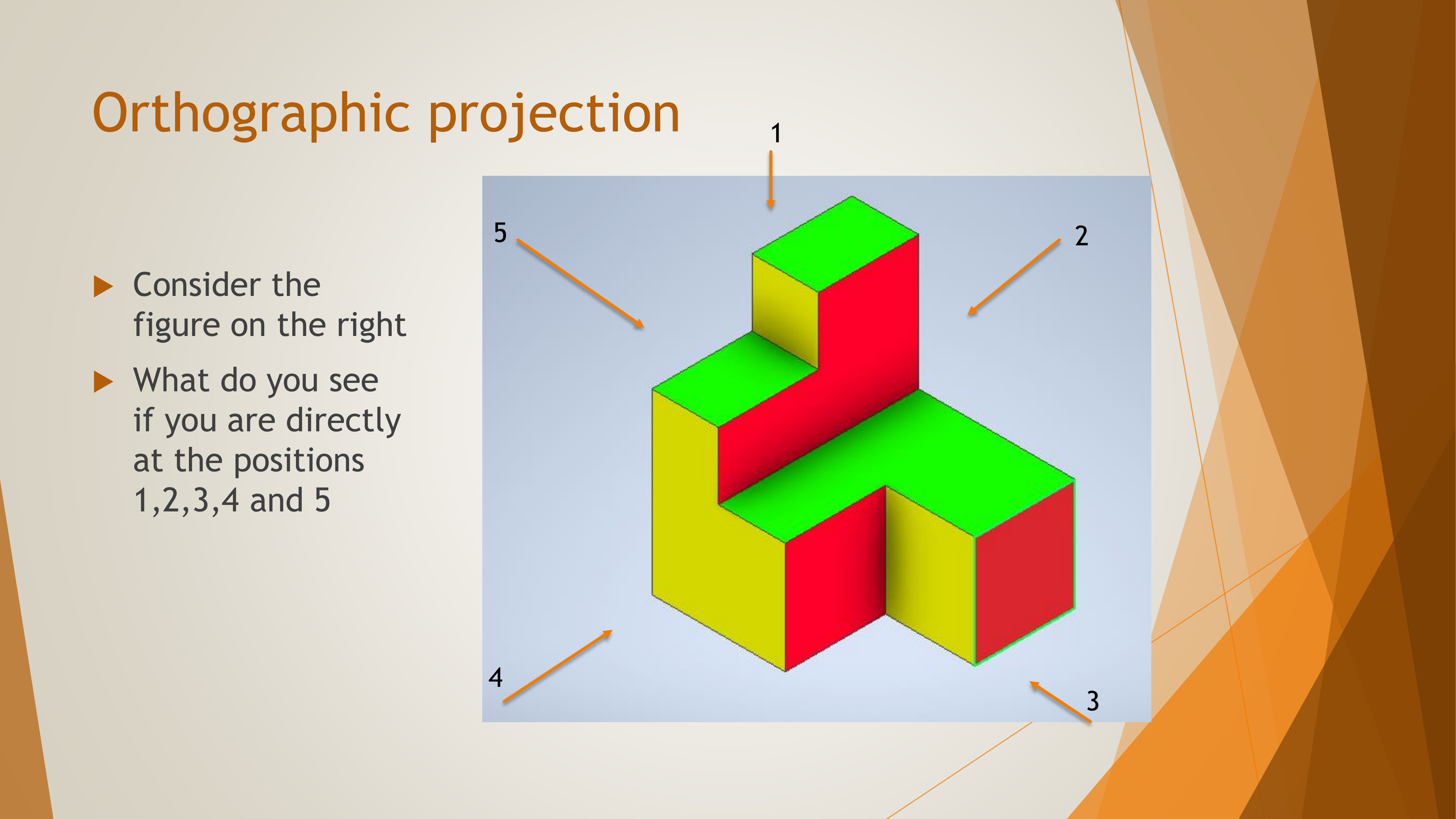
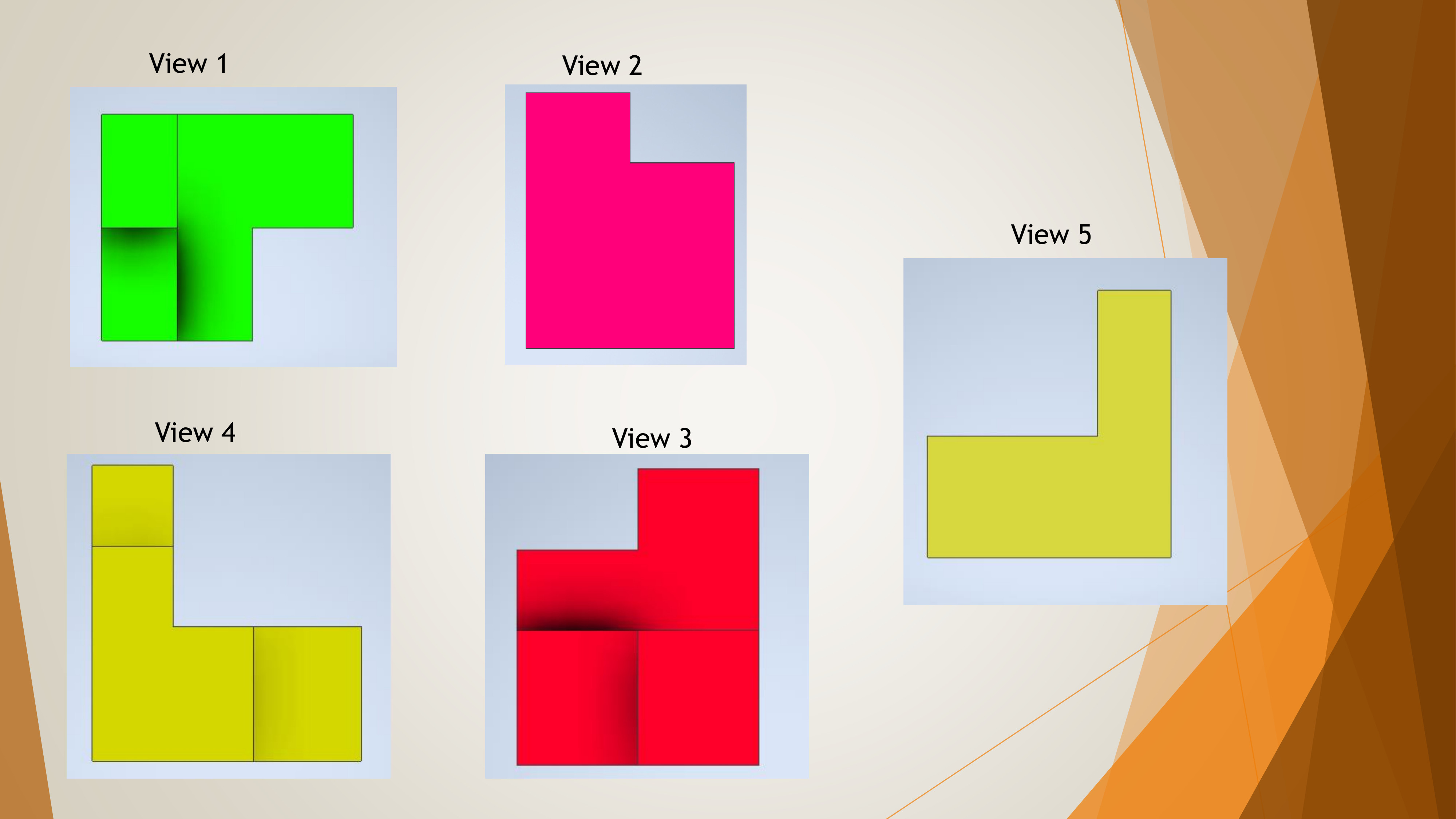
Identify and differentiate between the various views in orthographic projection.
Draw accurate orthographic projections from 3D objects, ensuring precision in dimensions and details.
Read and interpret orthographic drawings, displaying the relationship between different views and the 3D object.
Apply orthographic projection techniques to solve real-world problems, creating detailed technical drawings for engineering and architecture.
Note to the Learner
The figures used in this lesson are colored for the sake of visualization to better elaborate the concepts. Do not apply color to your drawings if you are using CAD software, and do not shade your drawings if you are drawing by hand manually.
Types of Orthographic Projection
There are two separate methods of drawing in orthographic projection:
the first angle projection and the third angle projection.
The latter method is becoming more popular throughout the world,
and may soon become the only accepted system in drawing.
At present, in Kenya, both methods are used. The building industry
mostly uses the first-angle projection, while other engineering
trades prefer the third-angle projection. Consequently,
the learner should be conversant with both these methods and their differences.
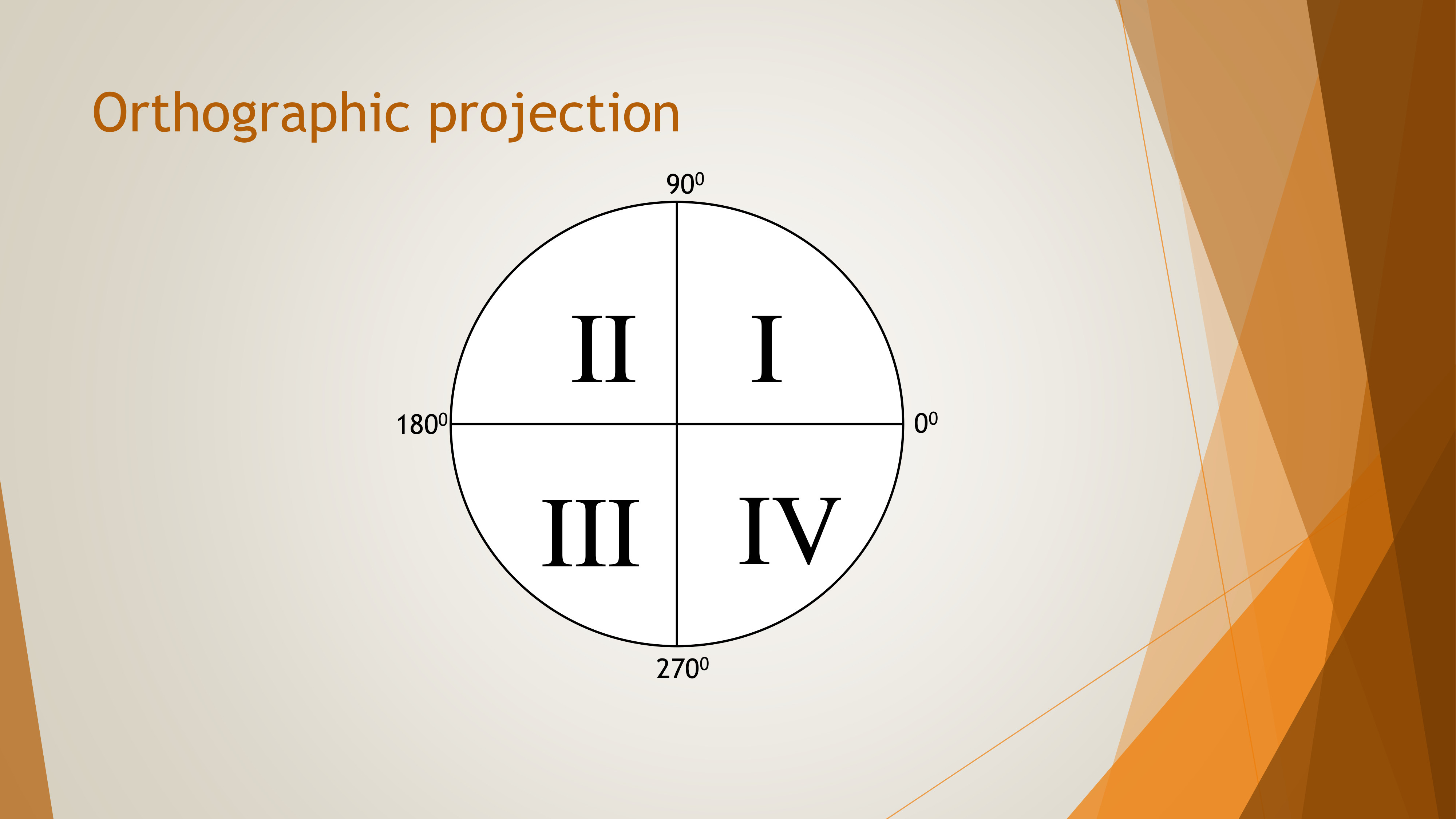
The names first angle and the third-angle are derived from mathematics.
A derived angle is divided into four right angles thus forming four equal quadrants.
The first angle is from 0 to 90 degrees in the first quadrant and the third angle is from 180 degrees to 270 degrees in the third quadrant.
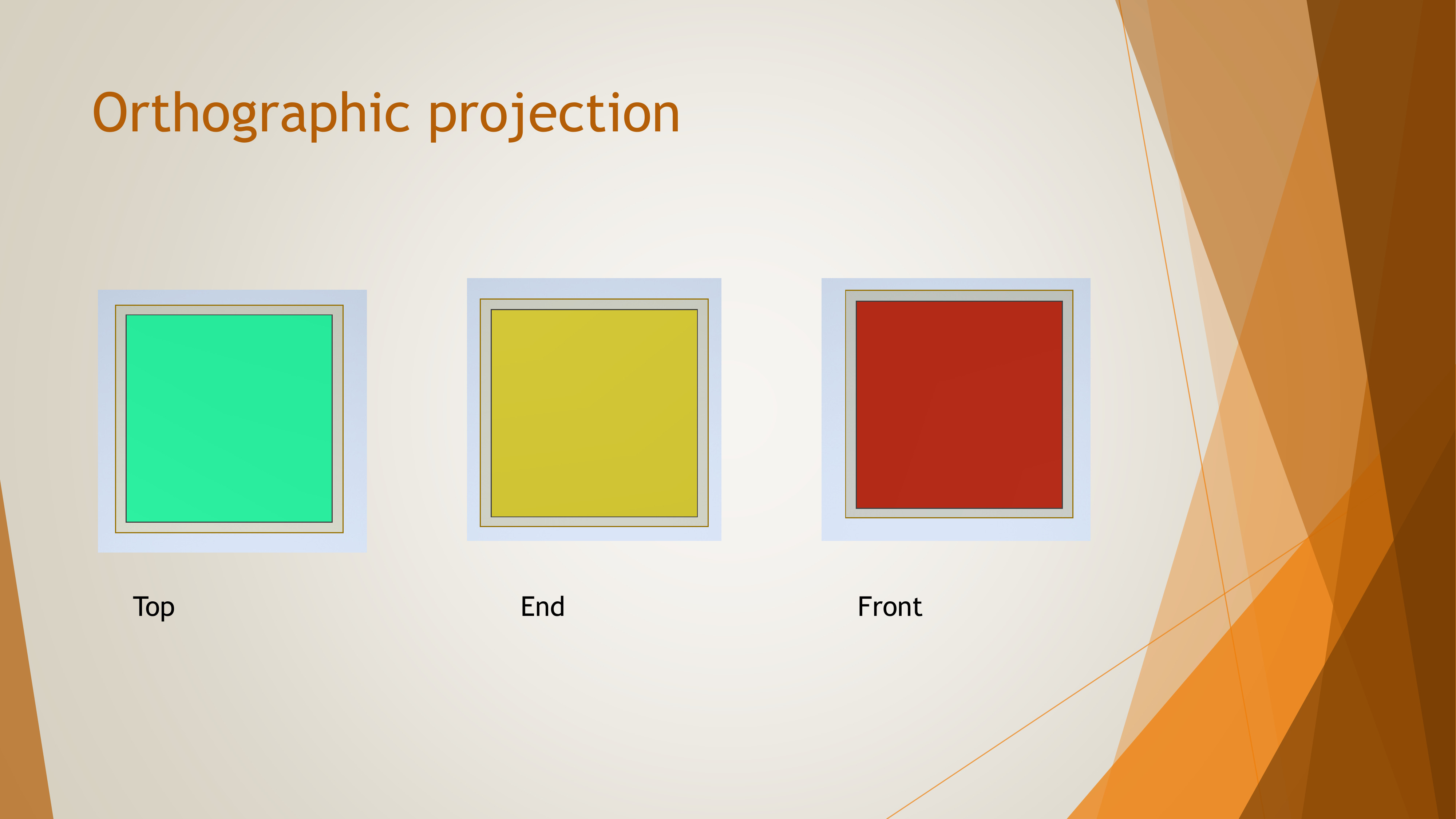
Views in Orthographic Projection
The views used in orthographic projection are:
Top View (Plan)
Front View (Elevation)
Side (End) View
Sectional Views
Auxiliary Views (in various situations)
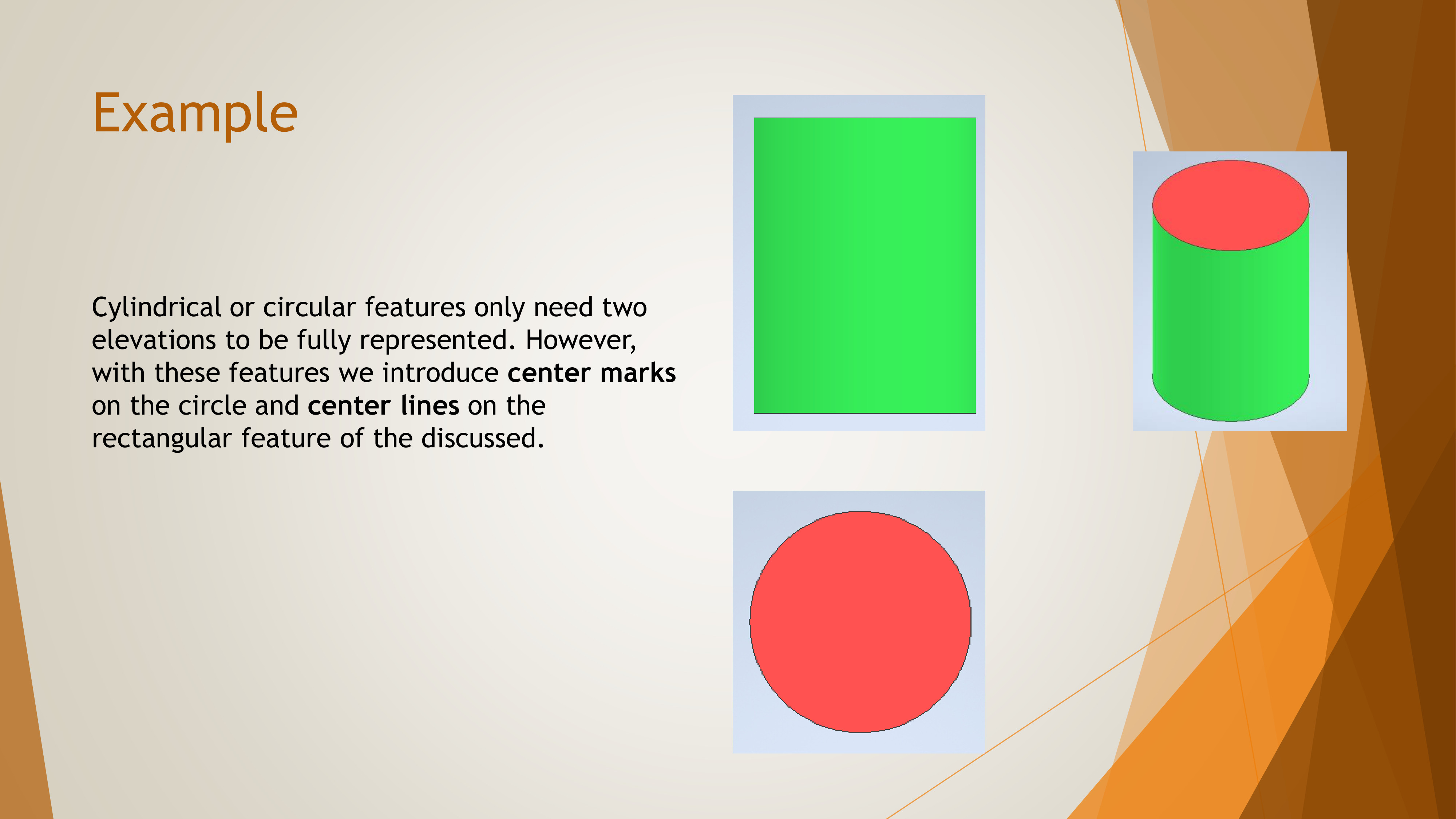
The front elevation displays height (H) and length (L),
the end elevation displays width (W) and height (H),
and the plan elevation displays length (L) and width (W).
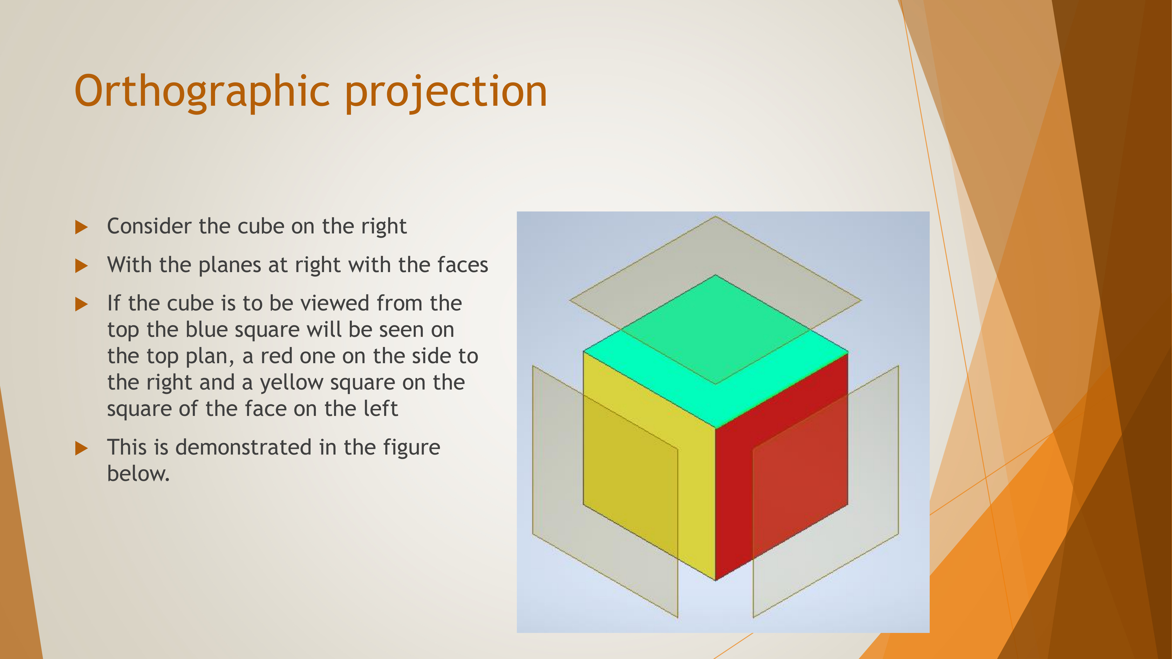
Forms Of Orthographic Projection
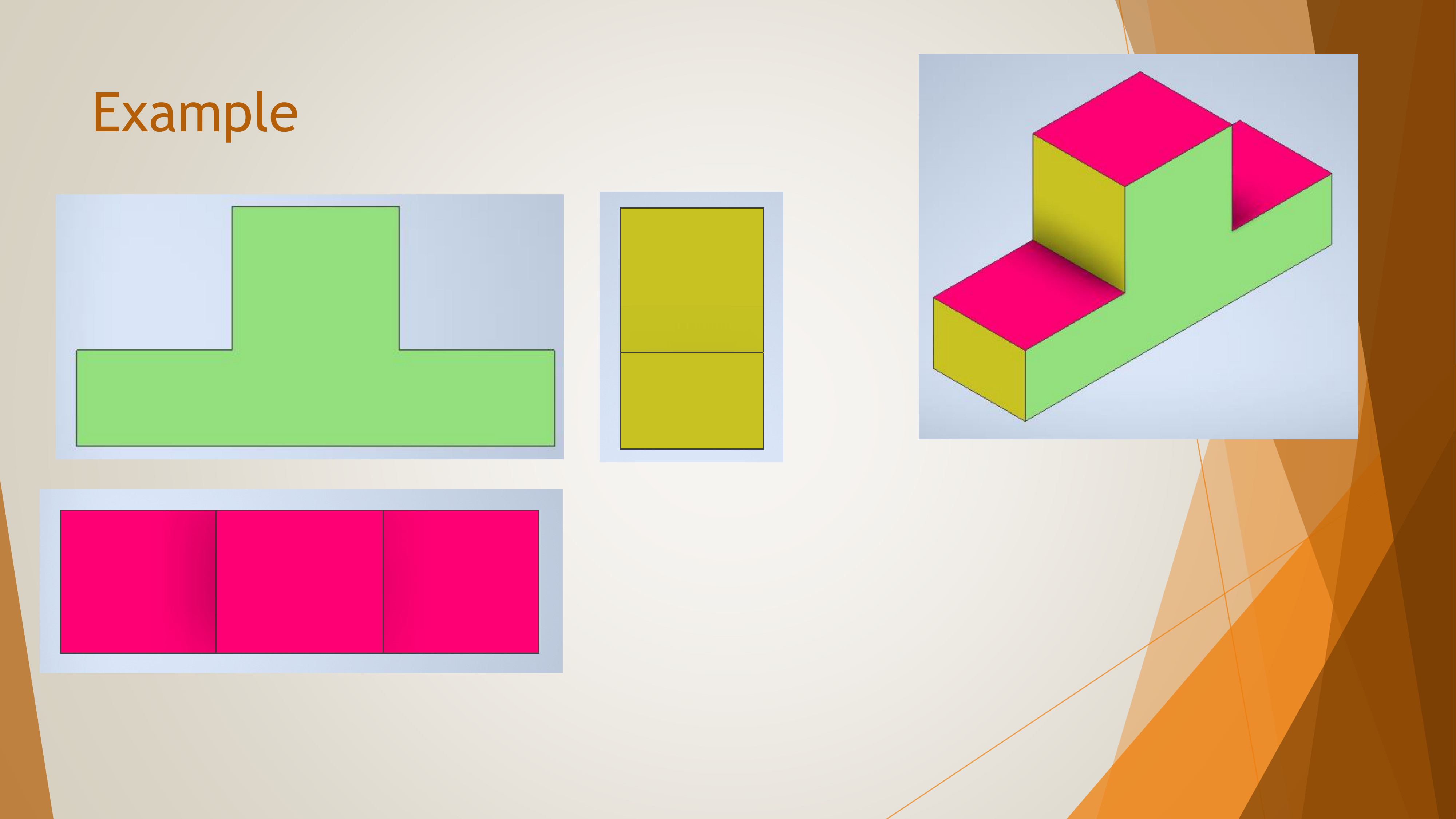
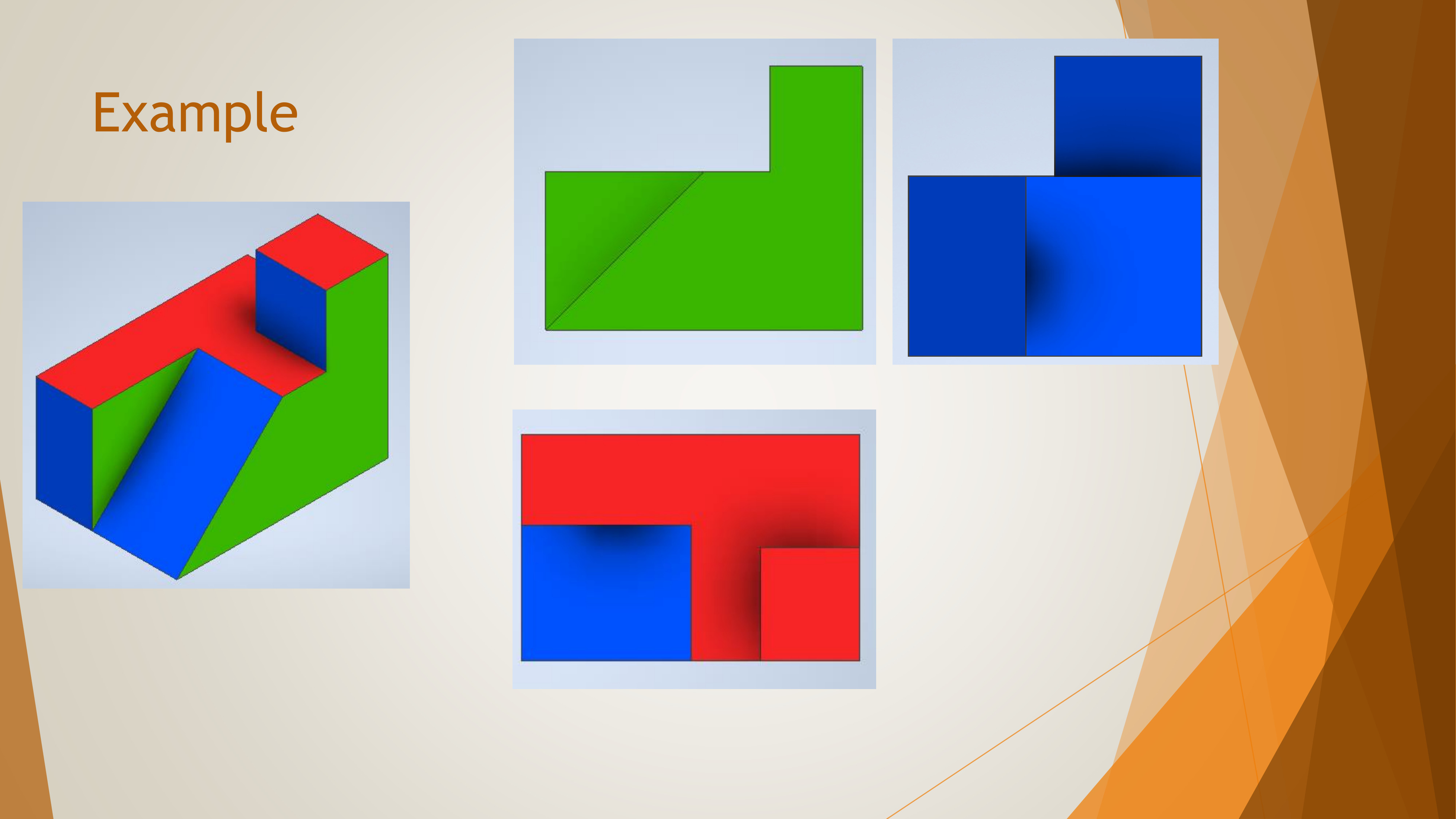
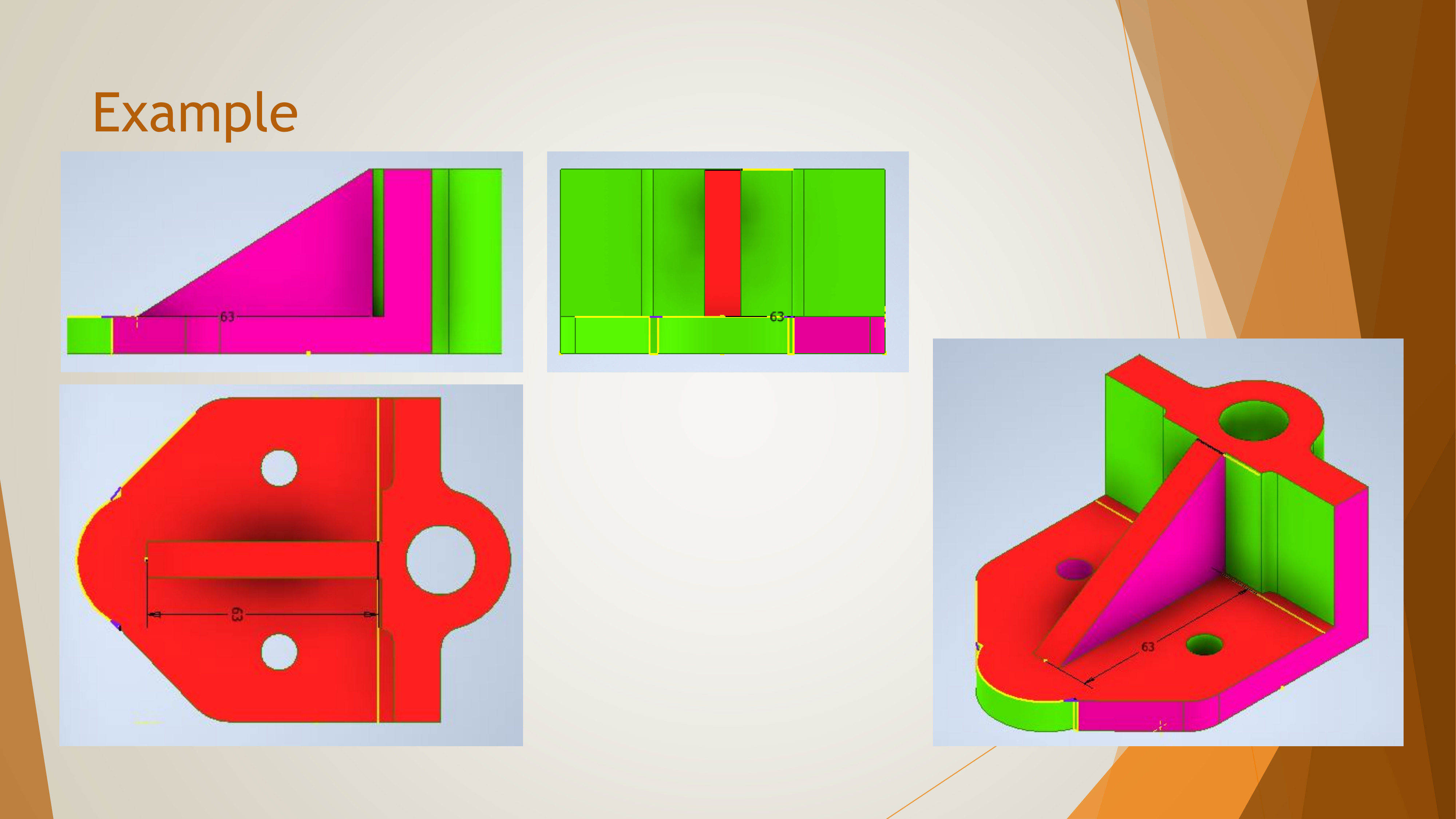
Orthographic projection overcomes the drawbacks of difficulty in drawing circles and curves on 3-sided objects.
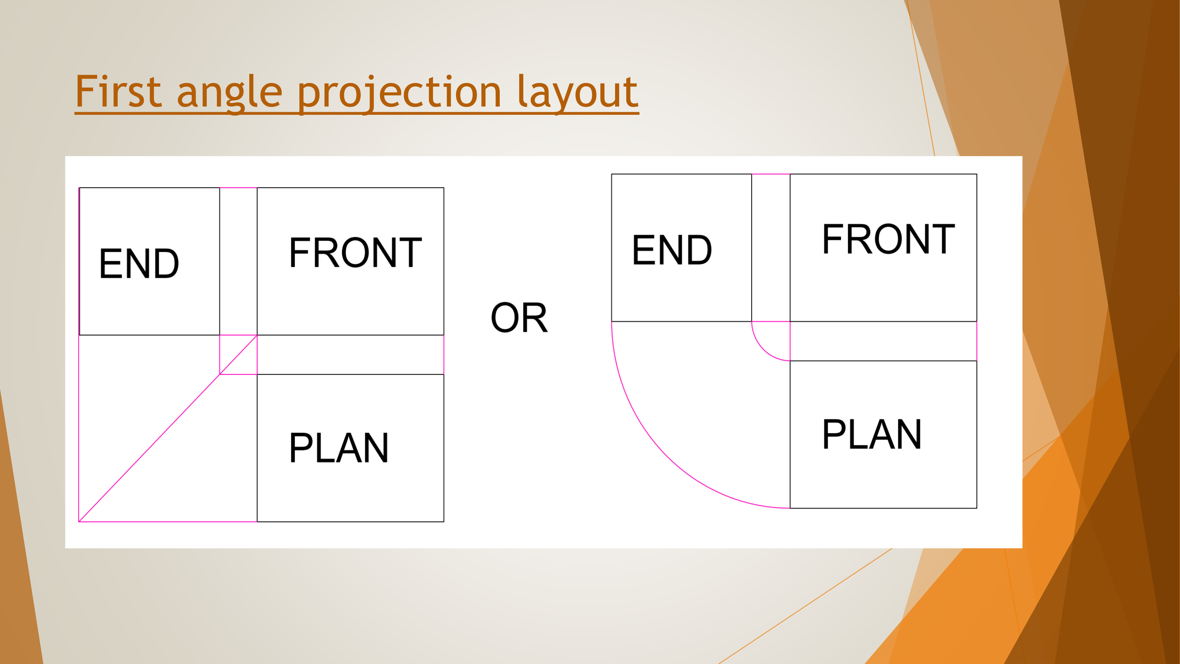
The key difference between the first and third angle projections is the relative positioning of views.
The first angle projection: this form places the object in the first quadrant,with the plan below the front elevation and the end elevation on the left or right side.
The third angle projection: this places the object in the third quadrant,
with the plan above the front elevation and the end elevation on the
left or right side depending on the view.
Differences between 1st angle orthographic projection and 3rd angle orthographic projection
Comparison Table
1st angle orthographic projection
3rd angle orthographic projection
1. The object is kept in the first quadrant.
1. The object is assumed to be kept in the third quadrant.
2. The object lies between the observer and the plane or projection.
2. The plane of projection lies between the observer and the object.
3. The plane of projection is assumed to be non-transparent.
3. The plane of projection is assumed to be transparent.
4. In this method, when the views are drawn in their relative positions, the plan comes below the front elevation, the view of the object as observed from the left-side is drawn to the right of elevation.
4. In this method, when the views are drawn in their relative positions, the plan comes above the front elevation, left hand side view is drawn to the left-hand side of the front elevation.
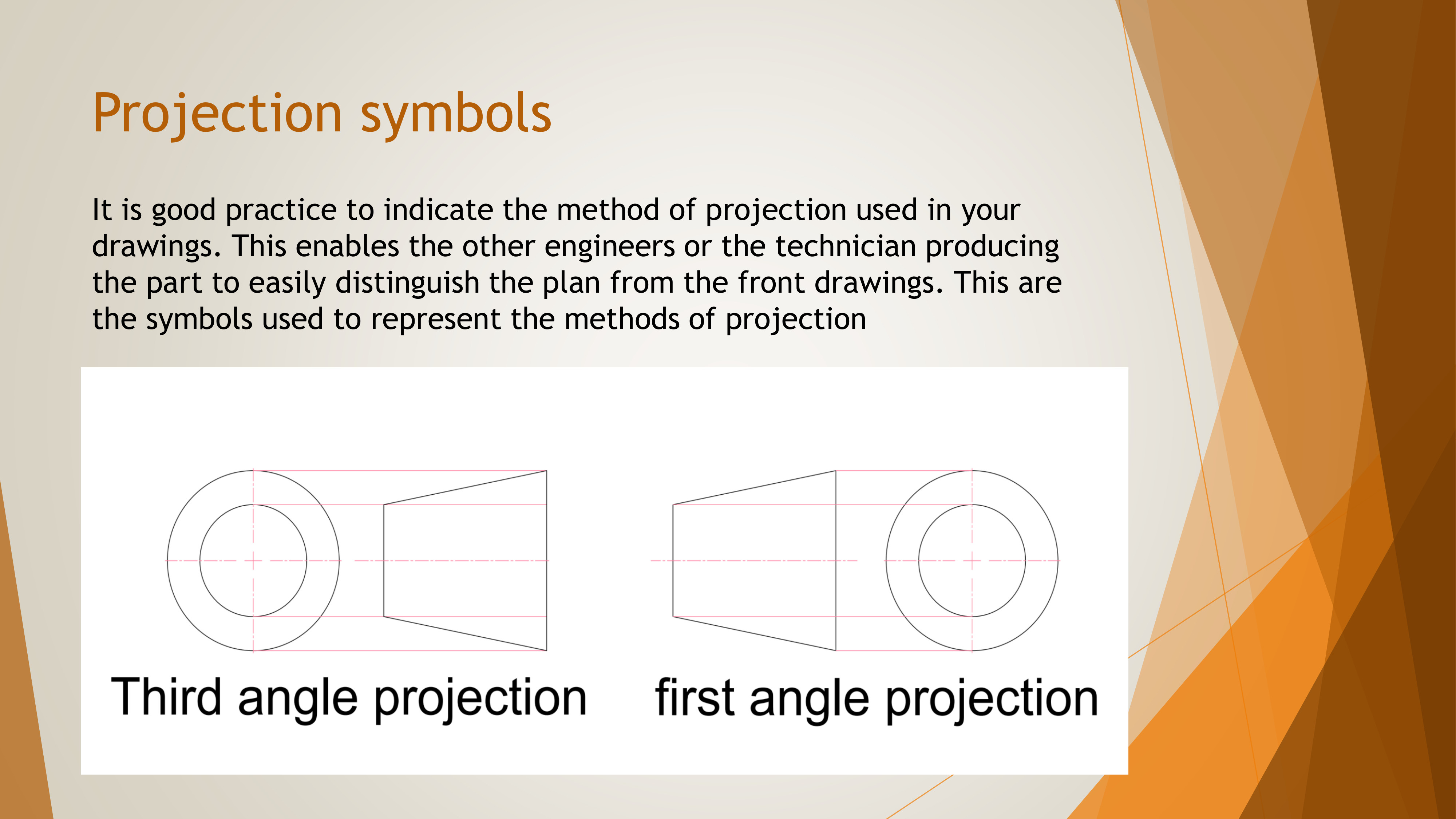
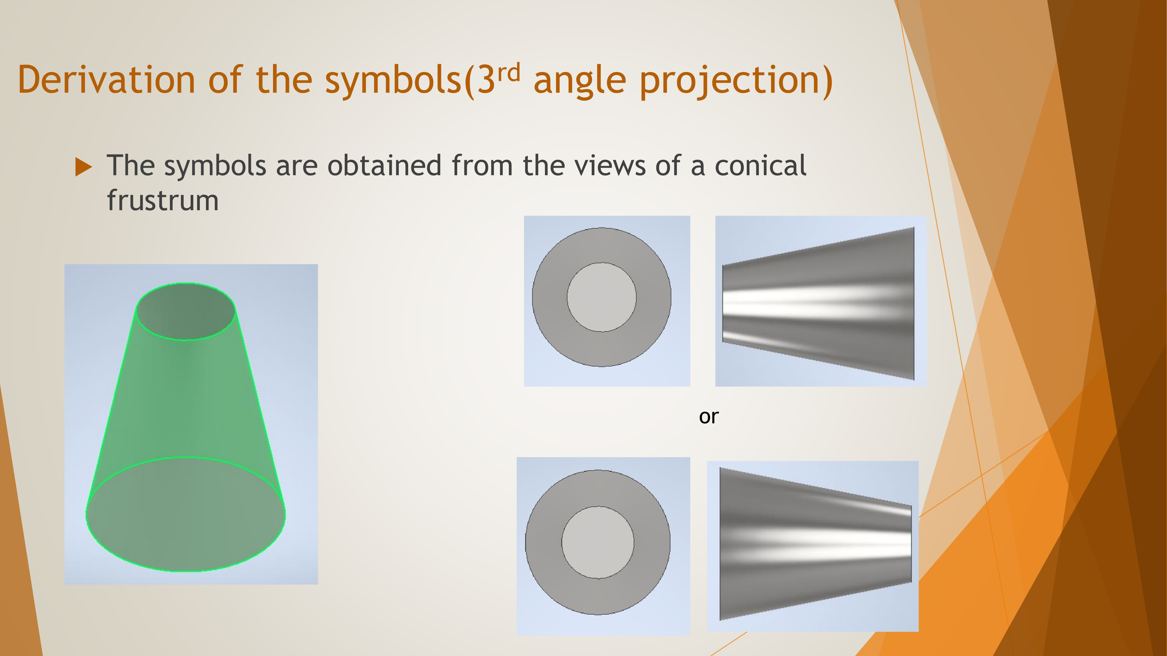
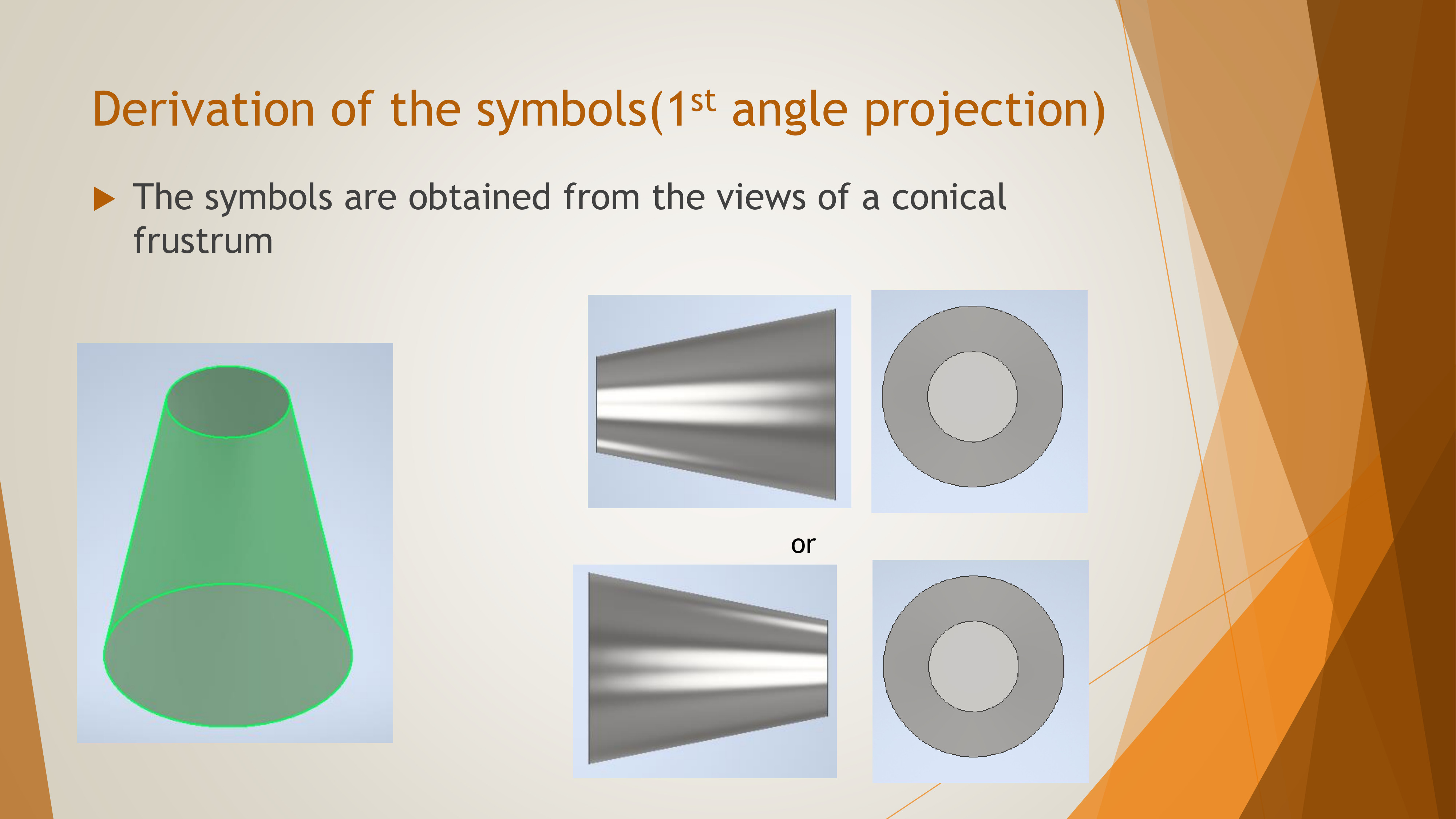
Projection Symbols
It is good practice to indicate the method of projection used in your drawings
to distinguish between plan and front views front drawings. The symbols are derived from the views
of a conical frustum and are used to specify the method of projection (first angle or third angle).
Below are the symbols used to represent the methods of projection:
Differences Between the first angle orthographic projection and the 3rd angle orthographic projection. Derivation of the symbols(3rd angle projection)
Derivation of the symbols(1st angle projection)
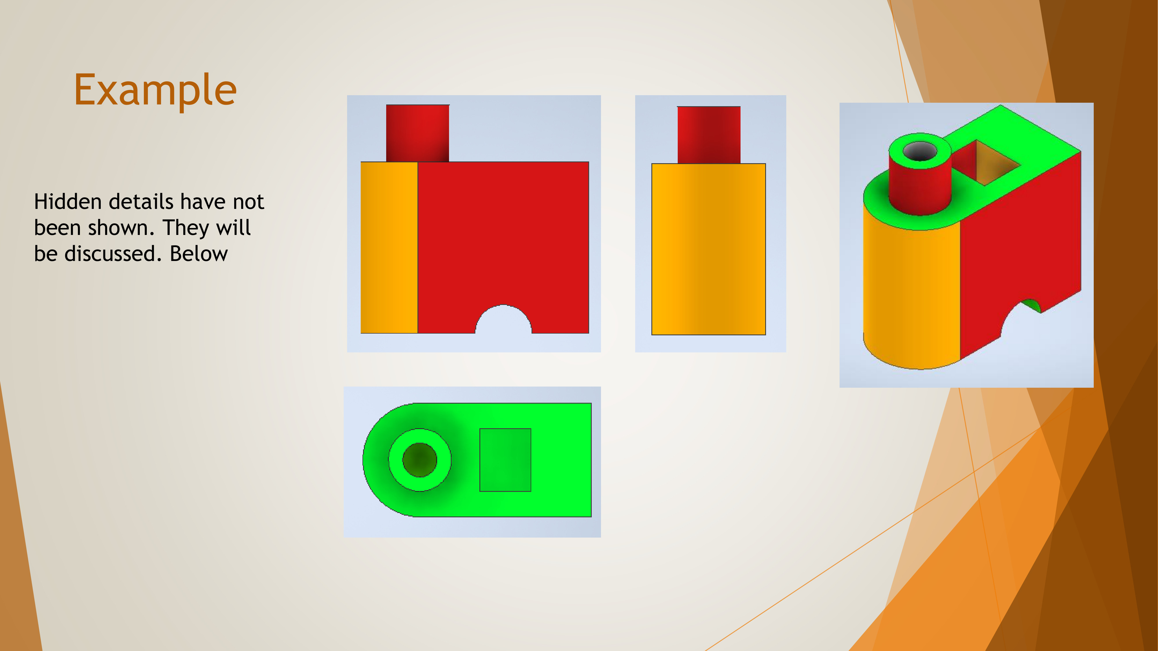
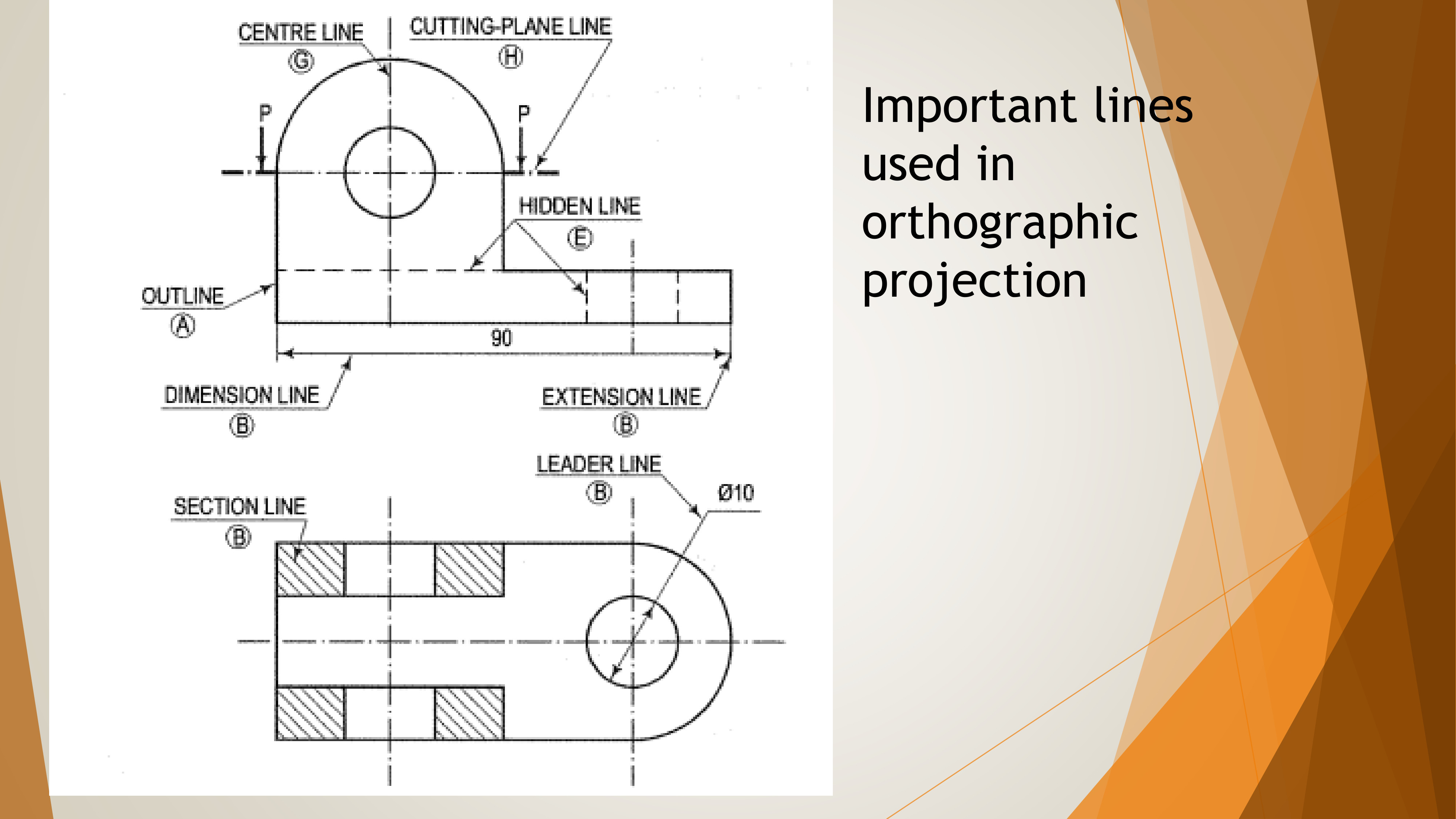
Hidden Lines in Orthographic Projection
Hidden details are represented by short dashed lines,indicating features that cannot be seen from a particular view but are necessary to define the part or assembly.Hidden lines are omitted when not needed to avoid clutter in the drawing.
Important Lines Used in Orthographic Projection
The following lines are essential in orthographic projections:
Center Lines: Represented by a long dash and a shorter dash,used to indicate the center of circular or symmetrical features.
Hidden Lines: Short dashed lines representing hidden details inside the object.
Frequently Asked Questions
Orthographic projection is a method of representing three-dimensional objects in two dimensions, where the object is viewed along parallel lines that are perpendicular to the projection plane.
The main types of orthographic projections are first-angle projection, third-angle projection, and isometric projection.
Orthographic projection helps in accurately representing the dimensions and shapes of objects from multiple viewpoints (top, front, side) to aid in manufacturing or construction.
Terms of Service
Terms of Service
Welcome to our tutorial website! By using our services, you agree to the following terms:
1. Use of Content
All tutorials, videos, and resources provided on this website are for educational purposes only. You may use the content for personal learning but cannot redistribute or sell any materials without permission.
2. Account Responsibility
When creating an account, you are responsible for maintaining the confidentiality of your credentials. You are also responsible for any activities under your account.
3. Community Guidelines
We encourage respectful and constructive interactions. Harassment, hate speech, or spamming will not be tolerated, and accounts engaging in such behavior may be suspended or banned.
4. Limitation of Liability
While we strive to provide accurate and up-to-date content, we do not guarantee the completeness or accuracy of all materials. We are not liable for any issues resulting from the application of the knowledge gained from this site.
5. Changes to Terms
We may update these terms occasionally. Continued use of the website after updates means you accept the new terms.
If you have any questions, feel free to
Privacy Policy
Your privacy is important to us. This website collects minimal user data and ensures that all information is handled securely. By using this website, you agree to the collection and use of information in accordance with this policy.
We do not share or sell user data to third parties. If you have any concerns, feel free to contact us.
About Us
We are a passionate team dedicated to providing high-quality educational resources and training materials.
Our mission is to empower learners with knowledge and skills to excel in their respective fields.